


I have worked with networked software for years, but for most of that time the network was something I used rather than something I really understood. I could open a socket, call an API, connect to an IP address, and continue with the part of the system I was responsible for.
When I started working closer to the power grid, this became uncomfortable. Network details were no longer hidden somewhere below the application. Ethernet frames, multicast, VLANs, gateways, industrial protocols, and utility networks appeared directly in requirements and discussions.
The difficult part was not learning what each term meant. I could read a definition of ARP or a description of a routing table. The problem was seeing how all these mechanisms formed one system, and then seeing how that system was used by substations, protection devices, control centres, and remote engineering tools.
This series is my attempt to build that connected picture. I want to begin with ordinary network machinery, reconstruct enough of it in Linux to make it tangible, and then follow it into the power grid.
In this post I will explain the plan and keep links to every part as it is published. The plan may change while I work through it, and this page will change with it.
Why networking in the power grid needs its own map
While writing A Developer’s Map of the European Power Grid, I kept running into communication at every level of the system. The last article, Where Software Lives in the Power Grid, made the gap even more obvious. A relay, an HMI, a gateway, and a control-centre service are all pieces of software, but the networks around them are shaped by very different physical jobs.
The vocabulary is dense, although the vocabulary itself is not the hardest part. The real difficulty is connecting ordinary mechanisms such as switching, routing, multicast, and redundancy to the events they carry. A frame in a substation might represent a protection decision. A remote connection might give an engineer access to equipment that controls real power.
When the networking foundation is fuzzy, grid protocols can look like a collection of arbitrary rules. When the grid context is missing, a generic networking explanation can feel detached from the work. I want this series to bring those two views together for software developers who are entering the energy domain.
How I want to approach the subject
I learn technical systems best when I can take a small version apart and rebuild it. That is the approach I want to use here.
Instead of beginning with a chapter called “ARP,” I would rather begin with two machines on one network and ask how one finds the other. Instead of introducing routing as a table of definitions, I want to place the destination somewhere else and watch the sending host decide that the packet has to leave through a gateway. The mechanism arrives because the problem makes it necessary.
Linux is a useful laboratory for this. Network namespaces can behave like separate hosts, veth pairs can connect them, a bridge can act as a switch, and another namespace can forward packets as a router. These experiments are small enough to run on one computer, but they expose the same decisions that appear in larger networks.
❓The question I want to keep asking is simple: what problem made this mechanism necessary?
The examples will be simplified on purpose. They are models for understanding packet paths and engineering choices, not reference designs for operational substations or utility networks.
The three acts
I currently see the series in three acts. Each one widens the system under investigation: first one host and its nearby network, then a substation, and finally the connections between substations, control centres, and remote users.
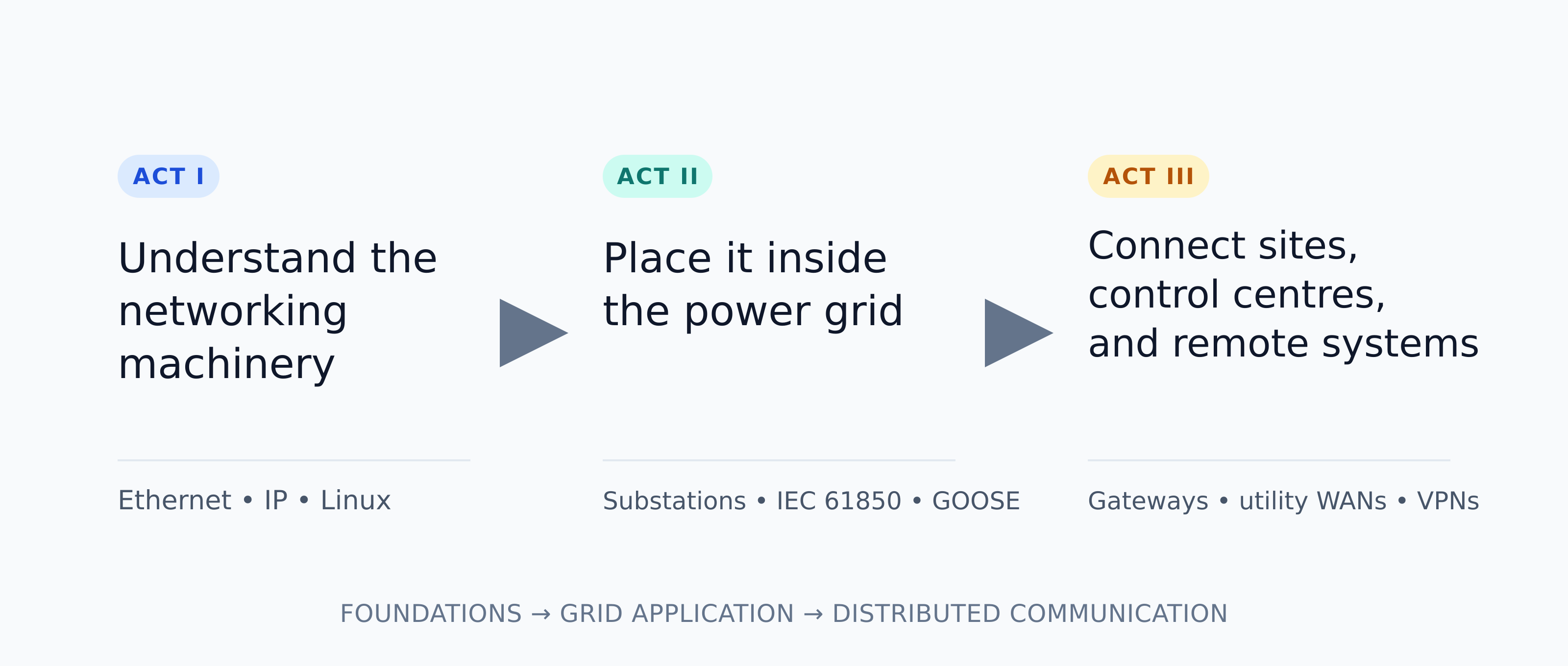
Diagram 1. Each act reuses the mechanisms established in the previous one and applies them to a wider part of the grid.
The division is useful for planning, although I do not consider it fixed. If an experiment shows that an article belongs somewhere else or deserves its own part, I will change the map.
Act I: Networking machinery for software engineers
Act I is where I fill the gaps in my own networking foundation. We start with the smallest useful network: two machines, a physical link, and a switch. From there we can see how Ethernet frames move, how hosts learn MAC addresses, and why ARP exists.
The first part begins at Layer 1, or L1. Copper and fibre carry electrical or optical signals, while Ethernet gives those signals a frame structure and an addressing model at Layer 2. I do not plan to turn this into an electronics course, but the physical layer matters because every packet eventually depends on a real medium, a negotiated link, and hardware that can fail.
Next, we break the local-network assumption by placing the destination somewhere else. This introduces gateways and routing for a concrete reason. Only after those ideas are visible from the outside do we open a Linux host and find the interfaces, neighbour table, routes, bridges, namespaces, and virtual links that implement them.
Linux comes last for a reason. Once the external network is clear, a single computer can reproduce it. Namespaces become hosts, veth pairs become links, a bridge becomes a switch, and a forwarding namespace becomes a router. That gives us a laboratory for the rest of the series.
Part 1: How Local Networks Work
Layer 1, Ethernet, MAC addresses, switches, and ARP
We will connect two hosts on one local network and follow a message from the physical link upward. The main question is deceptively simple: what has to happen before one machine can send an Ethernet frame to another?
Coming first.
Part 2: How Packets Travel Between Networks
IP addresses, subnet masks, gateways, routing tables, and routers
The destination now moves outside the local network. We will follow the packet through the host’s routing decision, the default gateway, and the router that connects the two sides.
Planned.
Part 3: How Linux Builds a Network
Interfaces, neighbour tables, routes, namespaces, veth pairs, bridges, forwarding, and TUN/TAP
We will rebuild the first two parts inside one Linux machine and inspect the objects that the kernel uses to represent the network.
Planned.
Act II: Networking inside the power grid
Once the ordinary machinery is clear, I want to bring it into a substation. This is where familiar networking ideas begin carrying unfamiliar consequences. Ethernet and multicast are still Ethernet and multicast, but now the traffic can describe measurements, status changes, or protection events.
A small substation model should make this easier to reason about. We can place an IED, an HMI, a gateway, and a station bus on one diagram, then ask why the network is segmented, which traffic is multicast, where time matters, and what happens when a link or switch fails.
Articles I currently plan
Building a Tiny Substation Network
A compact network with representative devices, traffic paths, VLAN boundaries, and the practical reasons behind them.
Why IEC 61850 Is Not One Protocol
A map of the different jobs hidden behind one standard, including configuration, client-server communication, fast events, and sampled measurements.
Rebuilding GOOSE From First Principles
An attempt to understand GOOSE by starting with the protection problem, then examining multicast delivery, repeated messages, timing, and failure behaviour.
Act II is planned. I will add links here as the articles are released.
Act III: Connecting the grid
A substation is only one island. The next step is to follow communication beyond it: toward a control centre, another site, or an engineer connecting from somewhere outside the operational network.
This is where routing, firewalls, wide-area links, tunnels, and trust boundaries meet. A diagram that says “remote access” can hide a surprising amount of machinery, so I want to open that path and inspect each boundary.
Articles I currently plan
From a Substation to a Control Centre
We will follow telemetry and commands across a simplified utility topology and identify the role of each network segment.
How Telecontrol Crosses Networks
This part will connect application protocols to TCP/IP, routing, firewalls, and operational constraints without treating the network as an invisible pipe.
Building a Secure Tunnel Into a Substation
A small WireGuard experiment will show what a tunnel actually creates, which routes change, and where encrypted traffic enters and leaves the system.
Act III is planned. I will add links here as the articles are released.
What this series should make possible
My target is fairly modest: I want the network below an application to become something I can inspect and reason about.
When I see an unfamiliar architecture, I want to identify the local-network boundaries, understand why a packet follows a particular gateway, recognise where multicast is being used, and know which Linux tools can confirm my assumptions. In a grid diagram, I also want to connect those mechanisms to the physical role of a relay, gateway, substation, or control centre.
That level of understanding will not make me a protection engineer or a utility network architect. It should, however, make the conversations with those specialists much more useful and make network-related failures less mysterious.
Follow the series
I will use this page as the index for the whole project. As each article is published, I will replace its status with a direct link and update the plan if the investigation takes a different direction.
I am learning this subject in public. If you work with industrial networks, IEC 61850, utility communications, or Linux networking and notice that I have missed something, I would be glad to hear from you.