



Recently I started working on a networking series for software developers who enter the electrical-grid world and suddenly discover that the grid speaks in packets, interfaces, switches, routes, protocols and a suspicious number of acronyms.
Before going anywhere near IEC 61850, utility WANs or substation networks, I wanted to understand the ordinary networking machinery itself. Not only what a switch or ARP does, but why these things had to appear in the first place.
I could start with the OSI model. I have seen that diagram enough times in my life. The problem is that a finished diagram is very good at telling us where something belongs and surprisingly bad at showing why it exists.
So I had a more ridiculous idea.
Imagine that I am somewhere in medieval Europe. No copper cable, no fiber, no radio and definitely no Ethernet. I have stone towers on hills, and the only useful property I can rely on is visibility. If one tower can see another, I can make light visible or hide it.
Could I start from that and slowly rebuild a network?
This is not a historical reconstruction. I am not claiming that medieval Europe was one good standards committee away from IEEE 802.3. The towers are only a constraint. I want to begin with the smallest possible communication system, push it until it becomes uncomfortable, fix the new problem, and then compare the thing we invented with the machinery inside a real network.
That approach is much closer to how I like to understand systems. The finished technology often hides the reasons for its own shape. Broken and incomplete versions expose them.
In this post we will discuss the local part of the network. We will begin with physical signalling between two towers, then add more participants and see why frames, MAC addresses, switching, flooding, broadcast and ARP appear. Near the end we will come back to Linux and look at the same machinery on a real machine.
Two towers and one bit
I want to begin before packets, addresses and protocols exist at all.
Two towers stand on neighboring hills. Tower A can see Tower B directly.

Diagram 1. Our entire network consists of two towers with direct visibility.
Tower A wants to send one piece of information to Tower B. The bridge is closed, for example.
But even that sentence is already too advanced for our network. We do not yet have a way to move a single bit between the towers.
The simplest thing I can invent is a lantern with a shutter. During a fixed interval the light is either visible or hidden.
light visible = 1
light hidden  = 0
So a guard can produce something like:
1 0 1 1 0 0 1 0
And the other tower can observe it.
This looks almost stupidly primitive, but it already contains the first real networking problem. An abstract 1 inside one system has to become something physical, travel through a medium, and be recovered by the other system.
In our case the medium is light through air. In Ethernet it may be an electrical or optical signal. Wireless uses radio. Real physical layers do not literally push abstract bits through a cable one after another. They deal with symbols, encoding, timing, synchronization, noise, attenuation, clock recovery and many other details that become a rabbit hole very quickly.
Even the lantern version immediately asks awkward questions. How long does one interval last? How does Tower B know where the sequence begins? What happens in fog? If the light stays visible for three intervals, how does the receiver know that it saw 111 rather than one long 1?
I am going to stop before our medieval guards have to invent signal processing.
The useful part for this article is that we have reconstructed the job of Layer 1: make information physical enough that it can cross one link and be recovered at the other side.
That works beautifully while our entire civilization consists of two towers.
Unfortunately, I want a network.
Adding the rest of the valley
So I add more towers.
Some can see each other directly. Some need a relay point between them. For the moment, imagine one local communication region where a relay tower has direct light paths toward several participants.

Diagram 2. Several towers now share one local communication system through a relay point.
The light can move bits across each individual path, but the moment several towers share the system, a stream like this becomes annoyingly ambiguous:
10110010...
Who is it for? Where does one message end and the next one begin? If the relay receives it, which path should it use? And if I later want to carry different kinds of data, how does the receiver know what is inside?
This is where the simple Layer 1 picture starts to break. The physical signal still matters, but I need structure above it.
Give the towers local addresses
I will start with the most obvious missing piece and give every tower a local identifier.
Tower A = 0A
Tower B = 0B
Tower C = 0C
Tower D = 0D
There is nothing magical about these values. My tiny kingdom does not need a 48-bit address space yet.
Now instead of sending naked bits, Tower A can send a structure:
TO:   0C
FROM: 0A
TYPE: MESSAGE
DATA: THE BRIDGE IS CLOSED
The relay no longer has to guess what the bits mean. There is a destination, a source, a description of what the payload contains, and the payload itself.
That structure is already suspiciously close to an Ethernet frame.
Our tower frame Ethernet equivalent What it is doing TO Destination MAC address Identifies the local recipient of the frame FROM Source MAC address Identifies the local sender of the frame TYPE EtherType Tells the receiver what kind of payload is carried DATA Payload Carries the higher-level data
Table 1. The fields I needed for the tower network have direct relatives in an Ethernet frame.
A real Ethernet frame has more machinery around this, and the signal on the wire has additional synchronization and encoding details. Our invented text header is obviously not its real wire format. Those details solve different problems, so I will leave them outside this model for now.
The important thing is that 0A, 0B and the rest are local link-layer identities. They play the role of MAC addresses. They do not tell us how to reach a tower somewhere on the other side of Europe. They let this local network move a frame toward the right participant.
This is roughly where Layer 2 enters the picture. We have stopped dealing only with signals and started dealing with frames and local delivery.
The relay starts remembering
The first version of my relay can be extremely lazy. Every time it receives a transmission, it can repeat the signal toward every other light path. At the frame level, the result is that every frame becomes visible everywhere.
This is roughly the world of an old Ethernet hub. A real hub operates at Layer 1 and repeats signals rather than parsing Ethernet frames, which is one place where the tower analogy should not be pushed too literally.
But the relay is sitting in a very useful position. When a frame arrives from the western path and says:
FROM: 0A
it has learned something for free: whatever 0A is, the western path is how I just heard from it.
So the relay can remember that fact.
After some traffic its memory may look like this:
0A → western path
0B → northern path
0C → eastern path
0D → southern path
Now a frame addressed to 0C does not have to be repeated everywhere. The relay can send it only toward the eastern path.
This is the part where our relay has quietly become an Ethernet switch.
A switch builds a forwarding table by looking at the source MAC address of frames arriving on its ports. The source address is evidence. If a frame from 0C arrived through port 3, then 0C is currently reachable through port 3. Real switches also age these entries because networks change, cables move and machines disappear.
The destination MAC is used for the next decision. If the switch already knows where that destination lives, it forwards the frame through the corresponding port.
The destination that has never spoken
This was the first place where I caught myself giving the relay knowledge it had never earned.
Suppose its table contains only:
0A → western path
0B → northern path
Then a frame arrives from the west:
FROM: 0A
TO:   0C
The relay can refresh 0A → western path, because it has just observed that fact. But the destination field tells it absolutely nothing about where 0C is located. TO: 0C only describes what the sender wants.
So the relay has one honest option: try all the other paths.
It retransmits the frame everywhere except back through the path it arrived on. Every participant may see it, but only 0C should accept a unicast frame addressed to 0C.
Ethernet calls this unknown unicast flooding.
If Tower C later sends anything:
FROM: 0C
TO:   0A
then the relay finally gets real evidence. The frame came from the east, so it can learn:
0C → eastern path
Future frames for 0C can go directly there.
There is a subtle point here that I want to keep separate from ARP. Unknown unicast flooding means the sender already put a destination MAC address into the Ethernet frame, but the switch does not know which port leads to that MAC. ARP solves a different problem: the sending host may not know the destination MAC address at all.
In a normal fresh IPv4 conversation, ARP often causes the destination host to reply before the first IP unicast frame is sent. That reply also gives the switch a chance to learn the destination MAC. So you may not actually observe unknown unicast flooding every time you contact a new local IP address.
The behavior still matters. Imagine that Tower A already knows 0C, perhaps from an existing neighbour-cache entry, while the switch’s own forwarding entry for 0C has expired. Then A can send a perfectly valid unicast frame to 0C, and the switch may still have to flood it.
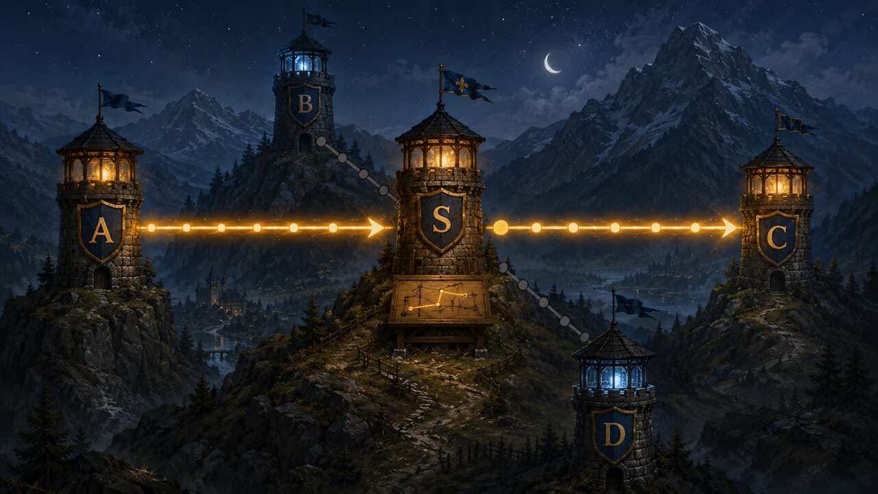
Diagram 3. The relay tower has become a Layer 2 switch by learning where local addresses are reachable.
The switch now has a useful memory, but Tower A can still be stuck for a completely different reason.
I know the IP address. I still cannot send the frame
Suppose an application on Tower A wants to send data to:
192.168.1.20
Let us say that this address belongs to Tower C.
For the moment I will also grant Tower A one piece of knowledge: it knows that 192.168.1.20 is on the same local network. How the host makes that decision belongs to IP addressing, subnet masks and routing tables, which is exactly the problem I want to pick up in the next part.
Tower A can create an IP packet for 192.168.1.20, but our local medium still does not forward an ordinary Ethernet frame by looking at that IP address. The Ethernet frame needs a destination MAC address.
And Tower A does not know it.
This is different from the problem we just had inside the switch.
Missing knowledge Who is missing it? Mechanism MAC → switch port The switch Source-MAC learning, with unknown unicast flooding when the destination is unknown IPv4 address → MAC The sending host ARP
I like this distinction because both failures can sound like “I do not know where C is,” while they live in different machines and are solved by different mechanisms.
ARP, the Address Resolution Protocol, exists to solve the second one for IPv4.
A local shout
There is a bootstrapping problem, though. If Tower A does not know Tower C’s MAC address, it cannot send Tower C a normal unicast Ethernet frame asking for it.
So I need one more local address in the tower world:
EVERYONE
A frame sent to EVERYONE is copied toward every participant in this local communication region.
Ethernet already has exactly such a destination:
ff:ff:ff:ff:ff:ff
That is the Ethernet broadcast MAC address.
Tower A can now send something equivalent to:
Who has 192.168.1.20?
Tell 192.168.1.10.
The Ethernet destination is the broadcast address, so the switch floods the frame through the local broadcast domain. The switch does not need to understand the IP address in the question. In the ordinary forwarding model it is still doing a Layer 2 job: it sees a broadcast destination MAC and forwards accordingly.
Inside that Ethernet frame is an ARP message. ARP is not an IP packet, and the switch does not use ARP to decide where ordinary unicast Ethernet frames should go. ARP is a separate protocol carried directly inside Ethernet, identified by EtherType 0x0806.
Every IPv4 host in the local broadcast domain may receive the request. Most of them inspect it, notice that 192.168.1.20 is not theirs, and move on with their lives.
Tower C recognizes its own IP address and replies with its MAC address:
192.168.1.20 is at 02:00:00:00:00:0c
The reply can be sent as a unicast Ethernet frame back to Tower A because the ARP request already contained A’s addresses.
That reply does two useful things in two different places. Tower A can store:
192.168.1.20 → 02:00:00:00:00:0c
in its neighbour cache, while the switch sees a frame arriving from Tower C and can learn 02:00:00:00:00:0c → eastern port from the source MAC address.
Nobody had to teach the switch about 192.168.1.20. It still does not need that information for normal Layer 2 forwarding.
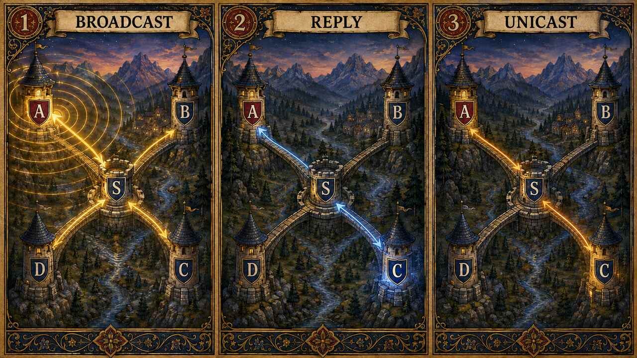
Diagram 4. Broadcast lets ARP discover the local MAC address associated with an IPv4 address.
This is the part of the experiment I find especially satisfying because we now have two small pieces of memory that look similar on paper but belong to completely different parts of the system.
Two different maps of the same local network
Tower A may remember:
192.168.1.20 → 02:00:00:00:00:0c
That is host knowledge. On Linux it lives in the neighbour table. For IPv4, ARP is the mechanism that normally creates and refreshes this mapping.
The switch may remember:
02:00:00:00:00:0c → eastern port
That is switch knowledge. It was learned from the source MAC address of a frame that arrived through the eastern port.
The two tables answer different questions:
Machine What it knows Why it needs it Host IPv4 address → MAC address To build an Ethernet frame for a local IPv4 destination Switch MAC address → port To decide where to forward that Ethernet frame
This also makes the MAC and IP distinction less mystical.
A MAC address is useful for delivery on the current Layer 2 network. An IP address is the logical address of the packet’s destination in the larger Layer 3 system.
When A and C are sitting in the same valley, both addresses appear to identify the same machine, so having two of them can feel redundant. The redundancy is mostly an illusion created by the small example. Once the packet has to cross a router, the reason for both becomes much clearer.
For a local destination, A may build something conceptually like this:
Ethernet:
  dst MAC = 02:00:00:00:00:0c
  src MAC = 02:00:00:00:00:0a
  type    = IPv4

IPv4 packet inside:
  dst IP  = 192.168.1.20
  src IP  = 192.168.1.10
The switch cares about the Ethernet destination MAC when forwarding the frame. Tower C eventually receives the frame, sees that the payload is IPv4, and passes the enclosed IP packet upward.
The complete first exchange is therefore not one magic lookup. It is several small mechanisms cooperating:
Application wants to send to 192.168.1.20
            ↓
Host decides 192.168.1.20 is local
            ↓
Neighbour cache has no MAC for 192.168.1.20
            ↓
Host sends an ARP request in an Ethernet broadcast frame
            ↓
Switch learns A's source MAC and floods the broadcast
            ↓
C recognizes its IP address and sends an ARP reply
            ↓
Switch learns C's source MAC from the reply
            ↓
A stores 192.168.1.20 → C's MAC in its neighbour cache
            ↓
A puts the IP packet into a unicast Ethernet frame for C's MAC
            ↓
Switch uses C's MAC to select the correct port
            ↓
C receives the frame and extracts the IP packet
This is a simplified path, but it is finally a simplification I can reason with. Each table has an owner. Each address has a purpose. The switch never needs to resolve 192.168.1.20, and ARP never tells the switch which destination port to use.
Back on a real Linux machine
After spending enough time with imaginary towers, I wanted to see whether the same structure is visible without the analogy.
Linux exposes the host-side neighbour table with:
ip neigh
For an IPv4 neighbour, an entry can look like this:
192.168.1.20 dev eth0 lladdr 02:00:00:00:00:0c REACHABLE
There it is: the same IPv4 address → MAC address mapping that Tower A had to learn. The Linux neighbour table is more general than ARP and also contains IPv6 neighbour information, but for IPv4 on Ethernet, ARP is the mechanism we care about here.
The exchange itself is even nicer because we can watch it happen:
sudo tcpdump -i eth0 -n -e arp
If eth0 is not your actual interface name, which is very likely on a modern Linux machine because apparently eth0 was too easy, replace it with the real interface.
With no cached neighbour entry, contacting 192.168.1.20 should first produce an ARP request sent to the Ethernet broadcast address. Then the owner of that IP replies with its MAC address. After the mapping exists, the host can send normal unicast Ethernet frames.
If the neighbour entry already exists, the absence of ARP traffic is not evidence that the mechanism disappeared. Linux is simply using what it already knows.
🔎 Try it yourself: run
ip neigh, startsudo tcpdump -i <interface> -n -e arp, and then ping another machine on the same local network. If a cached entry prevents the ARP exchange from appearing, remove only that entry withsudo ip neigh del <IP> dev <interface>and repeat the experiment. Use a machine and network you control.
I will stop the Linux part here. Later in Act I I want to open one host properly and look at interfaces, bridges, network namespaces, virtual Ethernet devices and the rest of the machinery Linux piles underneath an innocent socket. Here I only wanted to verify that our medieval invention leaves fingerprints on a real machine.
Then I add another valley
So far everybody belongs to one local communication region. Broadcast can reach the whole group, and one Layer 2 system is enough.
Then I put another valley behind the mountains.
It has its own towers, its own local relay, its own broadcasts and its own local MAC addresses. Tower A cannot simply shout an ARP request across the mountains and expect all of Europe to participate.
Still, Tower A needs to send a message there.

Diagram 5. The local-network model stops being sufficient when the destination belongs to another network.
This is where my local-network model finally runs out of road.
I could try to connect both valleys into one gigantic Layer 2 domain and let broadcasts spread farther and farther. Then I could keep adding valleys until one ARP request lights half the continent. Apart from being a rather beautiful medieval spectacle, it would also turn every local broadcast into everybody else’s problem.
The cleaner solution is to let each valley remain a local network and introduce a machine that knows how to move packets between networks.
That machine is a router.
And here the two-address idea starts paying rent.
If Tower A wants to send an IP packet to a host in the remote valley, the packet can keep the remote host as its IP destination. But the Ethernet frame used in A’s local valley is not addressed to that distant machine. It is addressed to the local router, the next machine that can move the packet closer to where it belongs.
Conceptually:
IP destination:       remote host in another valley
Ethernet destination: local router
The router receives the local frame, removes that Layer 2 envelope, examines the IP packet, chooses the next route, and places the packet into a new Layer 2 frame appropriate for the next link.
This is the point where the medieval analogy also needs a new piece. A relay inside one valley was enough while everybody shared one local addressing and broadcast system. Communication between valleys requires a gateway that understands something larger than local tower addresses.
That larger system is what I want to rebuild in Part 2: IP addresses, subnet masks, the decision that a destination is local or remote, default gateways, routing tables and routers.
The towers got us surprisingly far, but the mountains finally forced us into Layer 3.
Which we cover in the next part!
Stay tuned!
Series Hub
Networking in the Power Grid for Software Developers

I have worked with networked software for years, but for most of that time the network was something I used rather than something I really understood. I could open a socket, call an API, connect to an IP address, and continue with the part of the system I was responsible for.
References and further reading
Linux kernel TUN/TAP documentation, useful later when we rebuild networking machinery inside one Linux host
A Developer’s Map of the European Power Grid, the wider series context for software developers entering the energy domain